This is a description of the RoboRoos Robot Soccer team. I wrote this a long time ago and some of it is out of date although still an interesting read.
System
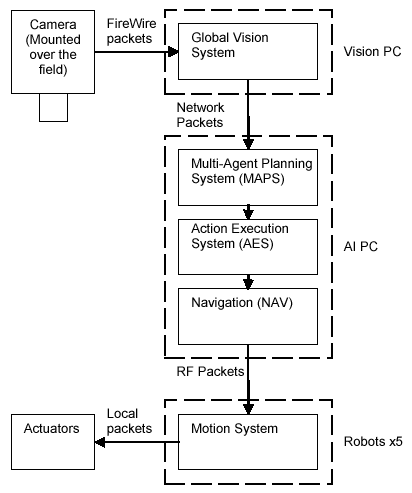
An overhead camera captures global images of the field. The vision system processes the images to identify and locate the robots and the ball. The state of the field is sent to the Multi-Agent Planning System (MAPS). MAPS is the highest level planner in the RoboRoos system, responsible for distributing the goal of the team (to score the most goals) amongst the individual robots. MAPS coordinates the RoboRoos by selecting an action and an action location for each robot. Some example actions include KICK and DEFEND. The MAPS actions and action parameters are now passed to the Action Execution system (AES).The RoboRoos system is a layered set of subsystems that each perform different tasks. The flow diagram (opposite) shows how the system is laid out overall. To give an overview of the system lets quickly follow the flow of the information from the camera to the robots actuators (motors).
The MAPS actions are interpreted by the AES system. Each action has a set of appropriate parameters and a notion of the overall desired robot motion. The NAV module attempts to achieve the desired motion behaviour while avoiding obstacles. The NAV modules determines the immediate desired heading and distance for the Motion System. The Motion system accelerates and decelerates the robot to the desired heading and distance by creating force limited trajectories. This ensures wheel slip is kept to a minimum.
Mechanical Design
The 2002 mechanical design features an omni-directional drive system, a powerful crossbow kicker and a dribbler all in a compact and robust design.
Omni-Directional Drive
The omni-directional drive system allows the RoboRoos robot to be agile. This is because it gives three independent degrees of motion: two translational and one rotational. This means that the desired rotation and position can be achieved independent of each other, as opposed to a typical differential drive robot that can only translate in the direction to which the robot has rotated. Not only can the omnidirectional drive robots have the right heading when they reach their goal but also can move towards their goal without having to first orientate in that direction. This gives the RoboRoos a significant advantage over differential drive robots.
The RoboRoos omni-directional drive is implemented using three DC motors each with two castor wheels. Each motor is mounted at 120 degrees from each other. The wheels are placed at the extremity of the robot to prevent rocking. The wheels have a moulded rubber surface for good grip with the surface. A photo of the RoboRoos drive system is shown in the figure.
The DC motors are the MiniMotor 6 Volt 2224’s with mounted encoder. This motor has a recommended speed up to 8000RPM and continuous torque up to 5mNm. The gear ratio from the motors to the drive shafts is 4.2:1. When running at the peak recommended performance, the drive system is capable of an acceleration of 2.3m/s/s and a maximum velocity of 2.3m/s. To be competitive the robots are run at higher accelerations. This is typically between 3.0m/s/s and 4.0m/s/s dependent on the surface and the team that the RoboRoos are competing against. This implies a 50 – 80% torque overload of the motors, which is acceptable provided that thermal limits are monitored.
Crossbow Kicker
A kicking mechanism allows a robot soccer player to take shots at the opponent’s goal and pass the ball to other members of it team. The kicking mechanism for the RoboRoos is of a crossbow design and it is shown in the figure. In its “hard kick” mode, it can kick a golf ball at approximately 5.0m/s. A “soft kick” mode allows a kick of 2.0m/s. The kicking mechanism, while mechanically complex, uses only one DC motor to both retract and release the kicker. The following is a list of the major components of the kicker mechanism.
Striker – This flat plate strikes the ball.
Rack – The rack is joined to the striker and allows it to be retracted and released.
Elastic Cord – The elastic cord provides the energy storage. It projects the striker forward when it is released. (Not shown in figure.)
Slot – Two slots are cut in the striker for the hard kick and the soft kick.
Trigger – The trigger is engaged in the slot and holds the kicker until it is released.
Micro-switches – The micro-switches provide feedback as to the location of the striker.
DC motor – A single motor is used to retract and release the striker.
Swivel bracket – This bracket houses the gear train that connects to the rack.
Pinions – The pinions are located in the swivel bracket. A pinion engages the rack.
Claws – The claws at the front of the robot contain a local infrared ball sensor.
The kicker works as follows. The DC motor rotates the pinions clockwise to retract the striker against the force of the elastic cord. This retraction continues until the desired micro switch is closed (hard or soft kick) and then the striker’s rack settles back so the trigger rests in the slot. To release the kicker the swivel bracket lifts the pinion from the rack and then pushes the trigger until the striker is released. The stored force in the elastic cord now projects the striker forward to hit the ball.
Ball Control Mechanism
It is desirable for soccer robots to control and move the ball about the field without losing possession. In real soccer this is called dribbling. A RoboRoo has a ball control mechanism, generally called a “dribble ball”, that allows it to move the ball around the field. The ball control mechanism is shown in the figure. The RoboRoos ball control device is a rotating rubber cylinder that applies backspin to the golf ball when in contact. This backspin gives the ball motion towards the robot, and this effectively ‘holds’ the ball against the robot. A small DC motor drives the shaft onto which the rubber is vulcanised.
The RoboRoos ball control mechanism has two features. One feature is a 15mm gap cut in the centre of the bar. When the ball is located in this gap the RoboRoo has some control over the sideways motion of the ball. It has another benefit as the crossbow kicker gives a more accurate and powerful kick to a ball located in the centre of the ball control mechanism. The second feature is the screw shape cut into the rubber. This gives the ball a component of force towards the centre of the dribbler. The ball then becomes trapped in the centre gap.
Robot Electrical Design
Main CPU Board
The RoboRoos Main CPU board uses Motorola’s MC68332 32 bit microcontroller. This microcontroller executes the low level motor control loop. The major benefit of using this microcontroller is its built-in Time Processor Unit (TPU). The TPU has 16 channels (I/O pins) that can be configured independently for a variety of tasks, including quadrature decoding (QDEC), input capture (IC) and Pulse Width Modulation (PWM) generation. Except for the kicker mechanism, the motors have encoders for fast and immediate local feedback. The QDEC function removes the need for either the central CPU to process the incoming encoder signals or a dedicated FPGA / CPU for the task.
A separate semi-discrete H-bridge controls the voltage to each motor. This H-bridge consists of a MOSFET driver, two n-channel and two p-channel MOSFETS. The central CPU board has an external 256 kilobytes of FLASH and 128 kilobytes of RAM.
Batteries
The RoboRoo robots are powered by NiMH (Nickel Metal Hydride) 1000mAHr 7.2V batteries. (Made up of 6 x 1.2 Volt cells connected in series.) The batteries are split into 3 sets of two cells each. All batteries are located on the base of the robot, in the same plane as the drive system. (This gives the robot a low centre of mass which increases stability and lowers weight transfer across the wheels when accelerating.) Depending on the amount of work the robot does the robots will last from 5 to 30 minutes on one set of batteries. The RoboRoos use a custom built battery charger for charging the batteries. It can charge up to 12 sets of batteries at once.
Wireless Communication System
The RoboRoos receive broadcast communications from the central PC, informing them of the state of the field and the actions they should be attempting. As the environment is highly dynamic it is important that this communication has low latency and low error rate. At a RoboCup competition multiple transmitters are in use at any one time causing high levels of interference. This makes achieving a low error rate particularly hard. The RoboRoos use 250kbps 900Mhz spread spectrum RF transceiver modules from Innomedia.
Unfortunately the RF modules have a complex custom communication interface of multiple synchronous serial channels for transmit mode, receive mode and initialisation mode. The interface board uses a PIC16F873 microcontroller to hide this complex communication interface and allows the central CPU to communicate using standard UART serial. This makes easy conversion from the commonly used RadioMetrix modules. For our communication packet of 50 bytes the latency is approximately 6ms. Error rate are always low, for example at RoboCup 2002 they were always under 5%.
This is a high level of performance compared to the commonly used 418/433Mhz RadioMetrix RF modules by F180 league teams. Communications were found to be reliable (under 5% error) only at rates of 19.2kbps or less. This is approximately 13 times slower that the Innomedia system. Another disadvantage of this method is that only one transmitter in the competition area can use a channel at a time. Therefore only two teams can use these modules at any one time.
Vision
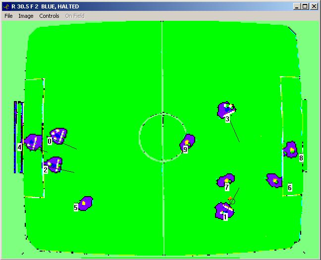
The vision system is responsible for determining the location of all the robots and the ball on the playing field. An overhead camera (mounted 3 metre above the field) sends a series of global images of the field to the vision PC for processing. Currently we use a Basler FireWire digital camera capable of 640×480 images at 88Hz in the Bayer2G format.
Currently the system runs at 640×480 (~5mm accuracy) at approximately 40Hz on a P4 2.0GHz. When properly calibrated the system does not give any false positives.When it comes to our robots the vision system must also determine their identification and their orientation. To achieve this our robots have white markers on top of them such as the small squares that represent the binary identity of the robot (robot 0 has binary 7) and the long stripe that represents the orientation of the robot. The orientation is determined by finding the second moment of inertia of the white stripes pixels.
Lastly the lens and perspective distortion must be corrected. The (x, y) position of all objects on the field are corrected. This information is now passed to the Intelligence systems.
INTELLIGENCE SYSTEMS
This program is responsible for ultimately determining the movement of the robots. The follwing figure shows this AI system. Note the actions given to each of the robots. Red is kick, Green is attack, Cyan is sweeper/cover. All graphics rendered using OpenGL.
The intelligence system has three modes: Real, Simulator and Playback. All modes use teh same intelligence system (MAPS, AES, NAV). Real mode connects to the vision system (network sockets) and sends comms packets. Simulator mode simulates the vision system and determines collisions. Playback mode plays back recorded matches.
MAPS (Multi-Agent Planning System)
The Multi-Agent Planning System (MAPS) is the highest level planner in the system, responsible for distributing the overall goal of the team amongst the individual robots. MAPS is responsible for the multi-robot coordination and cooperation by selecting an action and an action location for each robot. MAPS determines the team’s actions based on the current world model, the team goal and the currently available actions.
MAPS is a plan-by-communication system, as opposed to a plan-by-program system. In a plan-by-program system plans are represented as a sequence of steps to be followed. The robots attempt to follow these steps but may be unable to cope with unforseen contingencies. In a plan-by-communication system the robots determine how to achieve the sub-goal themselves. By using the MAPS sub-goal, but paying careful attention to local state, the robot is better able to complete its part in the plan. MAPS continually monitors the global state and does not rely on a robot to complete its action.
MAPS uses potential fields as the mechanism for determining action selection and action location. The potential fields can model the suitability of an action for the different agents, or be used to find a suitable action location. MAPS has a library of potential field functions and abstractions, where each field is a two dimensional array of values. A more positive value represents a more desirable action for an agent, or, in the case of determining action location, a more desirable location for that action. The following four types of potential fields are examples of the type of fields used.
* Basefield: This field represents favourable regions of the physical environment. The regions of the field that will always be favourable to the goals of the team are the most positive.
* Object Regions: These fields model physical objects on the field by representing an area of effect around an object.
* Clear Path: This is an abstract feature that represents clear paths to objects or locations. It biases regions that offer a line-of-sight path to the point in question.
* Distance: This is another abstract feature that represents the distance from objects, thus favouring action locations close to the robot or to a goal location.
It is the overlaying of multiple fields that gives an abstract goal-biased terrain map that provides the information to determine the robots’ sub-goals. By tuning the strengths and shapes of the component fields, MAPS can be tuned to give peak performance for a specific goal, or to act against specific opponent strategies.
Lets describe an example MAPS potential field. This one determines where to kick the ball to.
* Basefield: The field is ramped towards the opponents end of the field and off the walls. This encourages kicking towards the opponents goal.
* Object Regions: The opponent’s positions are given low values. This discourages kicking through them.
* Clear Path: Clear paths from the ball are extended using the above object regions. These represent where the ball can be kicked at.
* Distance From: This is the distance from the ball. This will control the distance we attempt a kick from.
* Object Regions: The opponent’s goal is given a high value to really encourage kicking at it.
AES (Action Execution System)
The Action Execution System is responsible for selecting the immediate robot behaviour. The field state and the MAPS assigned action are used as resources to determine this behaviour. The AES system fills in the details of the assigned actions from MAPS by decomposing it into a series of small tasks that can be performed using simple behaviours. The AES then decides on the immediate task to be achieved.
Each behaviour has a set of associated parameters and desired robot motion. Parameters associated with a robot include accelerations, application specific actuator state and desired repulsive strength of obstacles.
In a real soccer match the most important and complex actions that a field player performs is kicking and dribbling the ball. As such the kick action provides a good example of the role of the AES. The kick action sequence involves acquiring the ball then dribbling until the robot is lined up for the kick to the MAPS assigned location.
The AES breaks the kick action into a series of smaller tasks. These are:
1. Move to near the ball. This step moves the robot to near the ball at high accelerations and speeds. If the robot already controls the ball then skip to step 3.
2. Acquire the ball. Acquiring the ball is dependent on its position relative to the field and the opponent robots. If the ball is amongst other objects a modified version of navigation is used to acquire the ball, otherwise the robot drives directly at it.
3. Dribble until kick. Once the ball is acquired the robot must assume a pose that allows kicking to the MAPS specified location. AES chooses the appropriate motion to maintain control of the ball.
4. Kick the ball. Activate the kicking mechanism while maintaining kick angle.
NAV (Navigation System)
A soccer robot requires a navigation system so that it can achieve the desired motion while avoiding obstacles. Just like in human soccer a soccer robot may be removed from the field if it pushes players from the other team. A competitive navigation system must not only allow robust avoidance of the other players, but still allow the robot to move into and around cluttered areas. This is difficult due to the highly dynamic nature of the environment and the need for a real time implementation.
The AES system provides the desired pose and the relative avoidance strength for each obstacle to the NAV system. The NAV system determines the desired direction and distance for the robot to travel in. Obstacles may be physical objects such as the robots and the field boundaries. They may also be virtual obstacles that can be used to keep a robot out of a particular area.
NAV is a biologically plausible reactive navigation system that is appropriate to the highly dynamic environment. The different influences in the environment are represented using multiple schemas. Schema theory is a behaviour-based approach whereby overall robot behaviour results from the interaction of many simple schemas operating in parallel. In this navigation system, multiple schemas are represented by polar mappings that are centred on the robot. The Goal Direction Map represents the attraction of the desired goal location and the Obstacle Map represents the repulsion of the obstacles around the robot. The Motor Heading Map determined by a piecewise substraction of the Obstacle Map from the Goal Direction Map. The largest peak forms the desired navigation direction.
The complex problem of navigation is broken down into simple schemas that represent the different navigational influences.The NAV system has shown itself a capable system for achieving desired motion behaviour while competently avoiding obstacles in the highly dynamic environment. This is because:
- Reaction to environment change is fast as navigation is based on reaction, not on a plan.
- Navigation maintains competence even with poor behaviour selection by AES due to robust avoidance of obstacles.
The deficiencies of a reactive navigation system, local minima and non path optimal generation are generally not apparent. Local minima are not apparent as the global state is highly dynamic, meaning that problem states do not exist for long. Optimal path generation is wasteful, as the generated path will not exist for long, again due to the highly dynamic nature of the environment.
MOTION (Motion Control System)
The primary function of the motion control module is to ensure that the robot complies as closely as possible with the NAV requests without causing the robot to lose traction with the surface. The NAV module provides a desired direction of travel and a total length that remains to the goal location. The motion control software seeks to provide constant force acting from the wheel to the ground. Typically, this force is somewhat less than the normal force applied by the robot to the ground so that good traction is achieved. Consequently, the robot limits straight line acceleration and rotational acceleration, and must adjust speeds when manoeuvring so that the wheels can generate sufficient force.
Maintaining good traction with the ground means that the motion control system can adequately perform its other essential role: keeping track of the robot’s position between external sensor updates. In the highly dynamic environment significant rotation and translation can occur between external sensor updates. Furthermore as the global sensor information comes from a delayed source (Vision) the motion control system can account for self motion
during the delay period. By accounting self motion between updates and during sensor delays, the motion control system greatly enhances the accuracy of the robot’s interactions with the environment. It is critically important to time and aim kicks correctly. By using the immediate feedback from local sensors, the motion control software can execute timing critical functions with a precision beyond the other software modules.
An interesting functionality in the motion system software is that the point of reference can be changed for navigation commands. Typically, rotation takes place about the centre of the robot. Under direction from the AES, the motion control system can switch the rotation centre to an arbitrary point. This is applied to ball control. When the ball is directly in front of the robot, as detected by the local ball sensor, the motion control system can switch to rotating about the ball’s centre. This provides better control of the ball during dribbling operations.

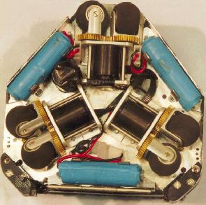

Diagram of the crossbow kicker mechanism.
Another view of the crossbow kicker mechanism.
Photo of the 2002 Dribbler.
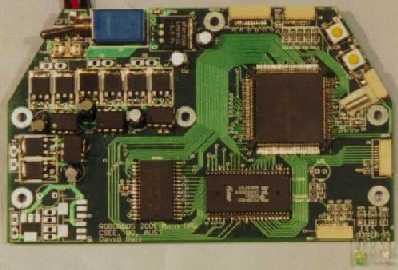
Photo of the 2001 Main CPU Board. Designing this was a part of my undergraduate thesis project.
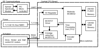
Diagram showing the major modules of the 2001 Main CPU Board.
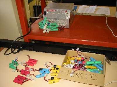
Battery Charger and Batteries (NiMH).

Photo of the RoboRoos Wireless Transmitter. Capable of 250kbs with under 5% error.
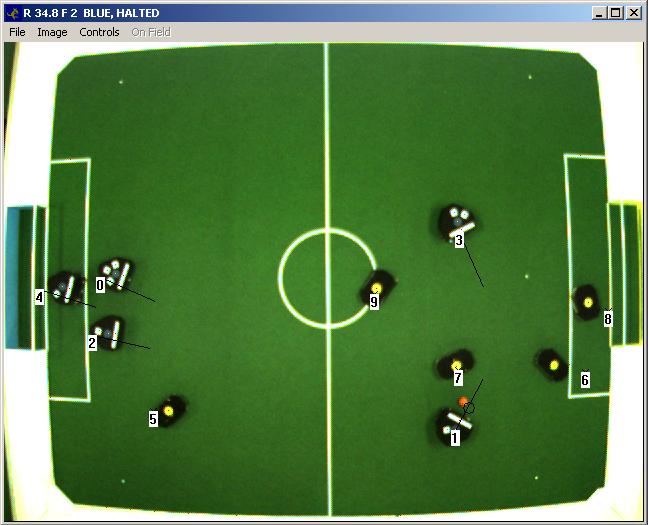
Global overhead image from our camera. Note that the positions of the robots and ball have been perspective and lens corrected.
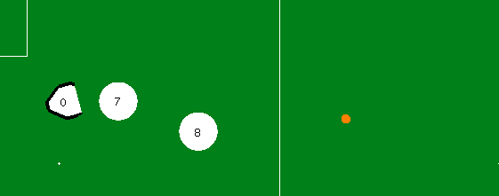
Colour Segmented blob image. Orange represents the golf ball, white the white markers, purple the black robot tops, green the field, light green the white field markings and walls, blue and yellow the blue and yellow markers respectively.
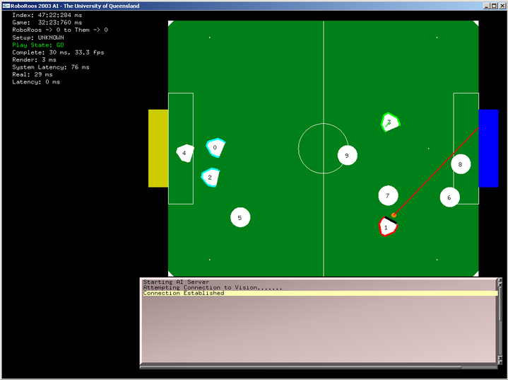
The Intelligence System window. Rendered using GLUT and OpenGL.
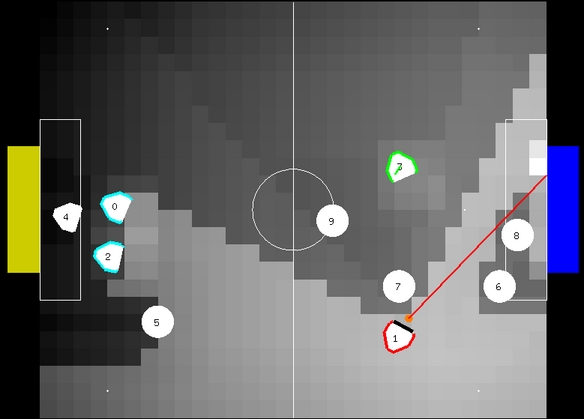
An example KICK potential field.
 |
 |
 |
 |
 |
 |
 |
 |
 |
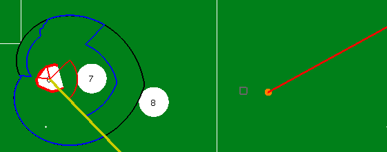
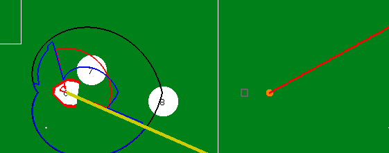
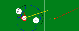
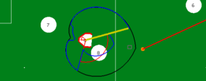
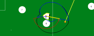
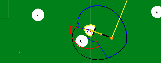
The RoboRoos navigation system in action. Goal Direction Map in Black, Obstacle Map in Red and Resultant or Motor Heading Map in Blue. (Polar Maps.) The grey square represents the desired goto (x, y) location. The yellow thick line represent the resultant heading (direction of movement) and length to travel. The resultant heading is the peak in the resultant map. (Note that the opponents (the circle robots) have had their top velocities capped to help show the navigation system in action). |
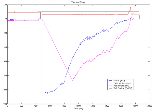
The RoboRoos control system in action. This graph shows the internal control system while the robot is acquiring the ball, turning with it towards the goal (~100 degrees) and then finally kicking the ball. Deltaf (delta facing) is the amount the robot has to turn the way that it is looking. Ball Control represents whether or not we have control of the ball as indicated by the IR sensor between the front claws. The kicker is started when deltaf (at ~1720ms) is zero and has kicked the ball when the ball control goes to zero (at ~1850ms). Deltaf changes rapidly by small amounts because of incoming corrections by vision and AI. Note that the control system realises that the robot will not be able to zero its velocity in time towards the end of the turn and so increases the turning acceleration. RotVel represents the robots desired rotational velocity.